The Circuit Pro
Project #1
Music-meter
with LM3914
Turn your music into light and let also your eyes enjoy it!
see project
Let's make it!
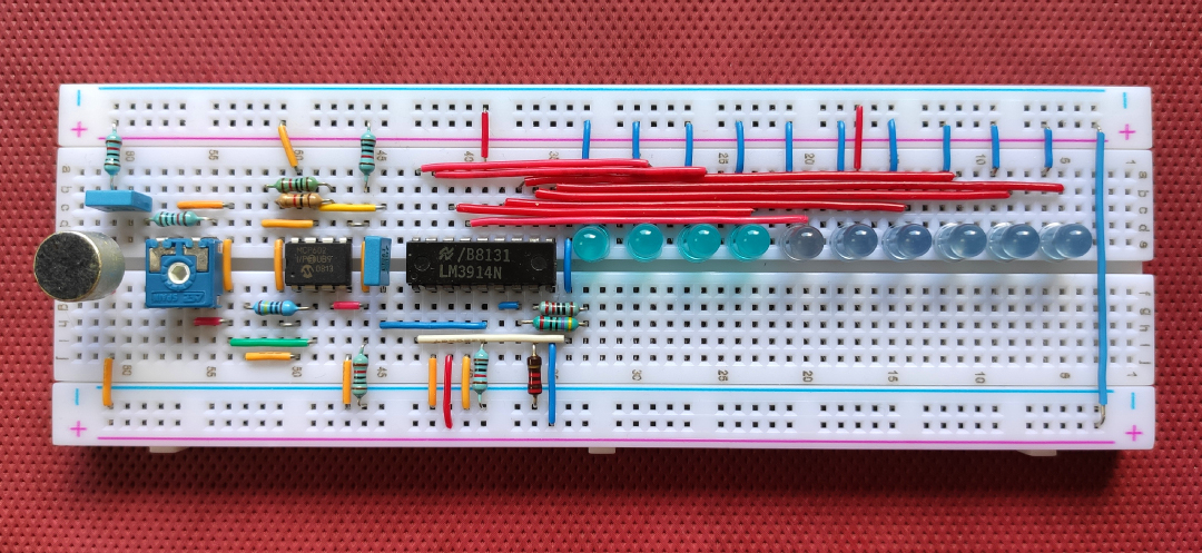
Breadboard implementation
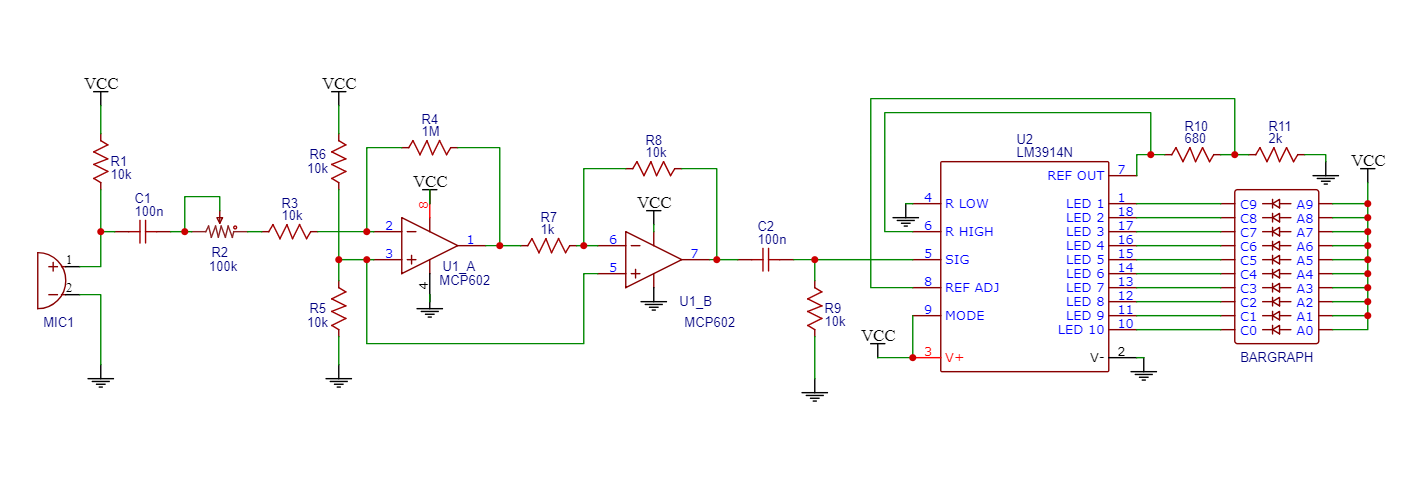
Complete schematic
Components list + best buy links
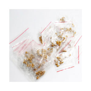
Resistors
1x 680Ω
1x 1kΩ
1x 2kΩ
6x 10kΩ
1x 100kΩ (trimmer)
1x 1MΩ
Resistors kit
link to Aliexpress
Buy now
I want to buy single resistors
100kΩ trimmer
link to Aliexpress
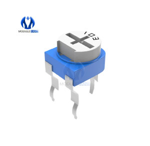
Buy now
Capacitors
2x 100nF
Integrated circuits
1x MCP602
1x LM3914
MCP602
link to Aliexpress
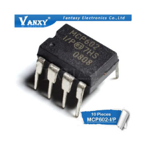
Buy now
LM3914
link to Aliexpress
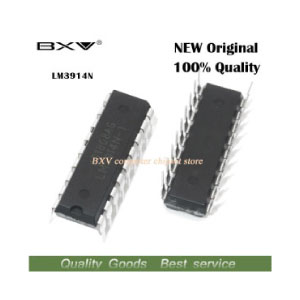
Buy now
LEDs
10x whatever color
Blue 5mm LEDs
link to Aliexpress
Buy now
Microphone
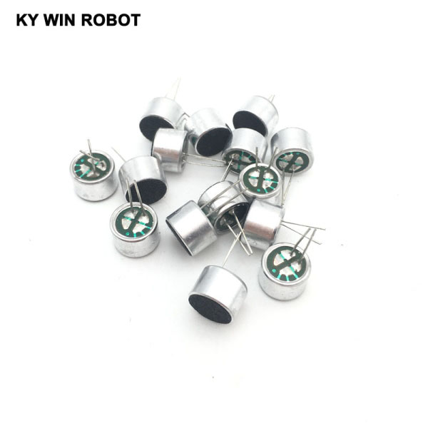
1x electret microphone
Electret microphone
link to Aliexpress
Buy now

Is this your first electronic project?
Take a look at the Get started section!
Circuit and components analysis
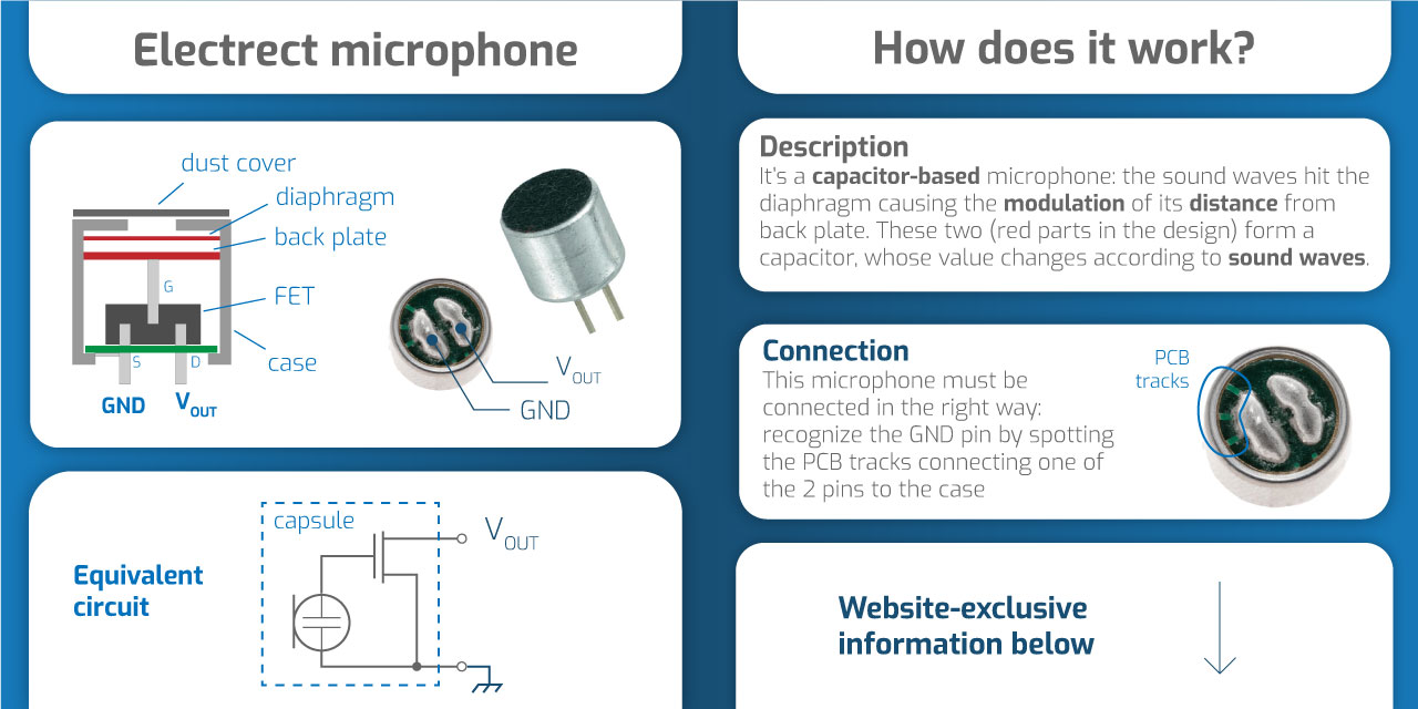
The Electrect material
It's a stable dielectric material, a permanently charged material that has embedded static electric dipole moment (one side is positiviely charged, the other one is negatively charged). This static charge is kept for hundreds of years.
The name comes from "electrostatic" and "magnet" and it's used in microphones with the goal of eliminating the need for a polarizing power supply.
The FET preamplifier
The voltage signal generated by the electrect itself is very low. To increase such signal, a Field Effect Transistor is used, in common source configuration (source connected to GND).
The electrect signal is connected to the gate of the transistor, while the output signal is taken from the drain. Note, however, that the transistor needs a bias (and a load) so the drain must be connected to the power supply by means of a resistor.
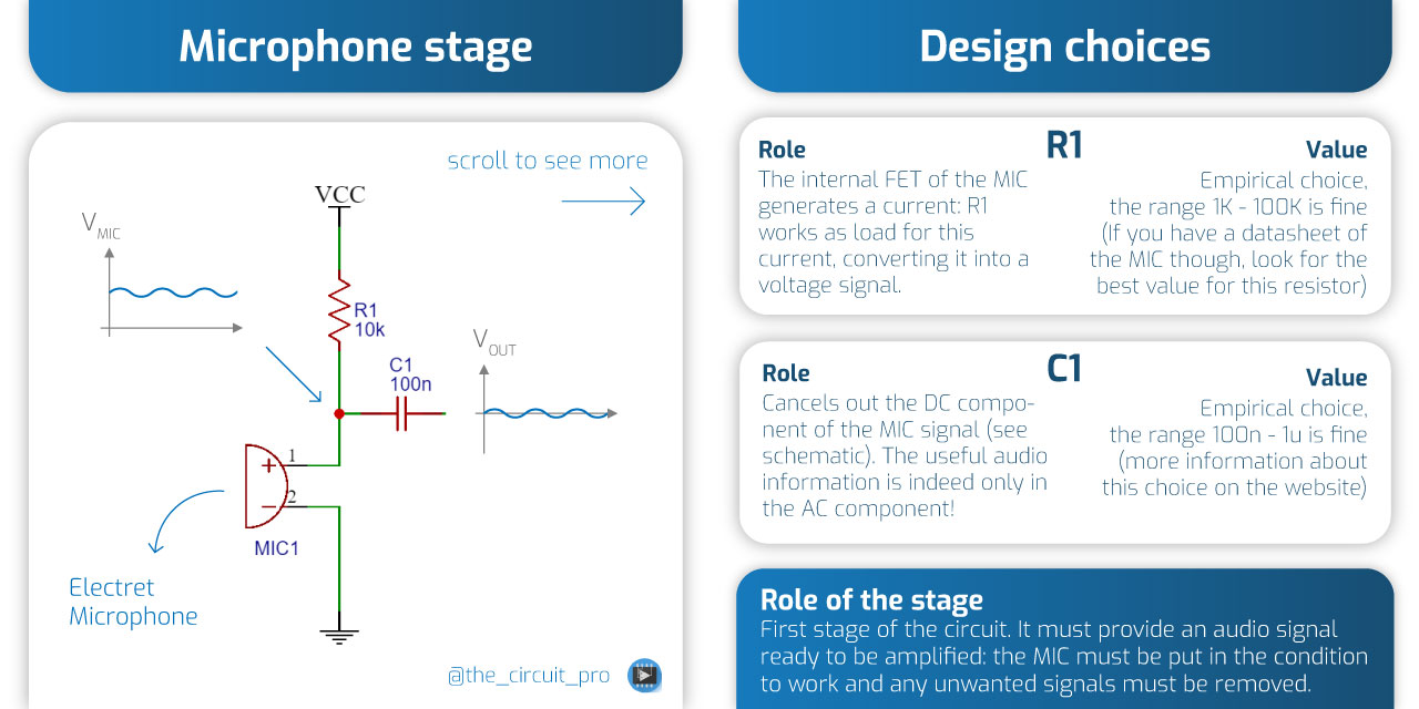
More on C1 choice
C1 makes up an high pass filter, together with R1 and the equivalent input resistance of the next stage. The cutoff frequency of this filter should not be too high, otherwise we won't be able to see the light response to low frequencies.
As a rule of thumb, let's keep the cutoff frequency below 100Hz, which in our case, considering R1=R3=10k (when the trimmer R2=0) sets a lower limit for C1 equal to 60nF.
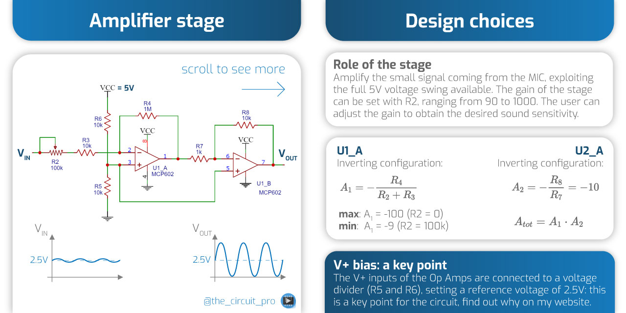
V+ bias
What the V+ bias does, is to shift the output of the Op Amps to 2.5V. That means, when the input is 0V, the output will be 2.5V.
Now, the amplified signal must be fed to the LM3914, that instead requires an input voltage = 0V when we have no sound, so that no LEDs will be ON. That's why I've added an high-pass filter (see next stage) to remove the 2.5V DC component at the output, right after this stage.
Does this make sense? Why am I first adding this bias and then remove it? This is actually a key point explained below...
The key point explained
If I connected V+ to GND instead of 2.5V (usual inverting configuration) I would theoretically obtain the same waveform at the input of the LM3914, where the negative part of the signal was cut.
The difference is that with V+ = 0V, the cutoff is due to the Op Amp output saturation, with V+ = 2.5V is due to the high-pass filtering, with the Op Amp still working in linear regime.
Every time an Op Amp saturates, it takes a certain time to recover into linear regime: this delay is very short but detrimental, slowing down the overall circuit response. This causes a bad result for this circuit, where we need high responsiveness to appreciate the LEDs effect: that's why I've used the 2.5V bias approach.
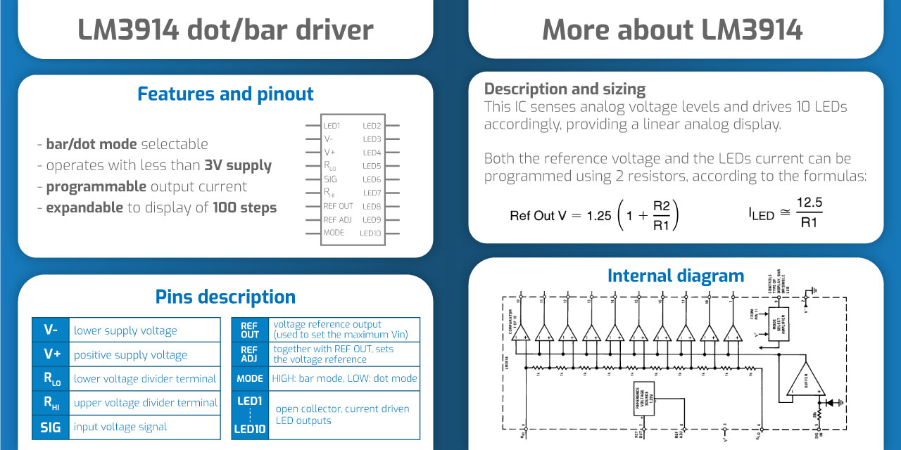
LM3914 datasheet PDF
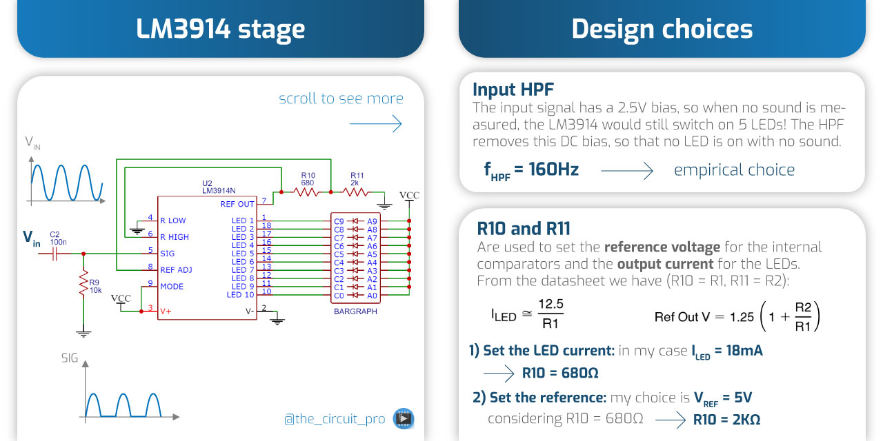
The voltage reference choice
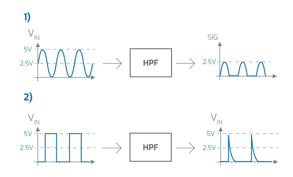
Refer to the image below.
When we analyze an analog stage, we usually do it by thinking about the signal as a sinusoid (case 1), in this case we can easily verify that with the maximum input sinusoid (5Vpp) we get, at the output of the HPF, a maximum signal of 2.5V. Still, I decided to set the Vref of the LM3914 to 5V (that is the maximum voltage I refer to at the input). Why?
Let's try to make more realistic considerations: the signal won't always be a sinusoid, as much as I don't like output saturation of the Op Amp, for this circuit that's something we have to deal with. The sound levels of a song are very widely spread, so either we decide to have low sensitivity (to avoid saturation) or we can keep it high accepting saturation (the visual result is better).
If we consider an time instant with high sound level in the song (e.g. drum hit) we can better think of our signal as in the case 2 of the image below. The response of the HPF will be now different, allowing the output to reach 5V on the rising edge of the square wave. This is the justification for such reference voltage!